Introducing Larsingerlogue CV-5000
Or how I gave Behringer FCV100 the reference power supply it deserves to use for CV-modulation with Korg Minilogue XD
If you're here to solve the problem and don't care for a story, keep scrolling, you'll get to schematics, breadboard pictures and an ingredient list.
There's also a short video montage for the even more impatient.
This is quite a different post than I usually make, if I'm allowed to call it usually anymore at all. In any case, I've been playing the keys in a band for a couple of years and have yearned for a proper synth to supplement my (6) master keyboards. Recently I acquired my first ever analogue synthesizer. It only took 40 years for the dream to come through. I found a 15% cheaper second hand "unused" Korg Minilogue XD. But I only had damper pedals to use with it. Half the fun of synthesizers for me is varying the low pass filter cutoff. It's what gives that cool swiping, buzzing or muffled sound depending on how you "turn" it. For that I needed another type of pedal, and not just a regular one.
The Minilogue has a ton of hand-controlled potentiometer knobs we can use for a multitude of parameters, amongst others the filter cutoff. However it does not have a regular 1/4" jack slot for expression pedals like keyboards usually have. It has a damper slot, but only for CC64 on/off (sustain on and off). What we want is a full, preferably analogue, range from 0 to 100%. Expression pedals are excellent for this since they're basically pot meters you turn with your foot.
What the Minilogue comes with are two 1/8" jack "CV in" ports. So I browsed the interwebz for "CV pedal" and found a bunch of alternatives. Since I'm eyeing a Behringer Poly D come fall I thought the Behringer FCV100 V2 pedal seemed a good deal. It's advertised as a volume pedal with a CV option, including reversing polarity. So I ordered one and excitedly unpacked it while the band leader ran out to buy the last 1/8" to 1/8" cable and a 1/8" to 1/4" adapter. I'd dutifully inserted a 9V battery and optimistically hooked everything up...
Nothing!
I tried both CV inputs, both polarities, tons of options on the minilogue, but still nothing.
When I got home - I plugged a 1/8" into the input port which according to the interwebs should "power it on". Still nothing from the CV output. And yes, I had measured the voltage on the 9V battery.
Note: I have had no ambition doing electronics "right" with this project, nor writing a proper tutorial with a "right" way of doing it. This is a story about fiddling around and getting things to work. It is not a tutorial in proper electronics, in fact almost the opposite. I have not bothered to look up facts or calculated things. This means people who know their way around electronics might find this article revolting. I'm sorry. It was a way for me to brush up on how things work and get something working quickly. DIY by fiddling around until it works. Again, sorry, but hopefully other learners might be inspired to both fiddle around and learn to do the calculations. There's even a gem of an insight in the end that only hit me while writing this post. 😇
The research
According to the interwebz, someone claimed to have gotten CV output when they had plugged an unconnected 1/8" jack into input 2, but showed no proof or measurements. The next answer was someone who had done some due dilligence and measured the output. Apparently it only works with instruments that feed a reference voltage from its control voltage (CV) input in order for the pedal to vary it.
So I dug out my trusty old multimeter and started the process of dusting off the parts of my brain still remembering reading "There are no Electrons: Electronics for Earthlings" ten plus years ago. I learned about what tip, ring and sleeve (TRS) for jack plugs are, and all the other variants. Measuring DC between the tip and sleeve of the unconnected side of the cable when pressing the pedal did absolutely nothing. Measuring resistance though showed a varying impedance of 0 through 50kΩ. If I flipped between TRS and RTS mode on the pedal it seemingly reversed the resistance on the ring, but the tip stayed fixed on 50kΩ in TRS mode. In any case, after some brain clearing with ChatGPT, I could conclude that the pedal in CV mode is only a 50kΩ potmeter and does not provide any of the sweet power from the (now useless) 9V battery I had inserted.
Note: I've left the pedal in RTS mode. In order to use both and reverse polarity there's more research and a V2 to be built. See closer to the end for a short rant about the factory presets in Minilogue XD.
I figured there has to be a way to provide that power even if the synth doesn't. So after a little more chatting with ChatGPT I figured I could dig through all my old cables and adapters to find an USB cable and adapter we're not using. I should be able to "inject" it's 5V DC voltage into the jack cable instead of relying on the synth to provide it. I dug through all my treasure drawers and found an USB mini-B 4-pin (?) to USB A cable and cut off the mini-B plug to reveal the two VCC/GND cables and two data cables. I found a couple of horribly old AC USB adapters and measured the DC from both via the cable's red (VCC) and black (GND) wires. One gave 3.3V and the other gave 5V. I happily threw the overdue 3.3V one in the "to recycling" bin and rubbed my hands together over the other. (Throwing out one old device should score me at least one plus in the wife's accounting system.)
Specifications
Of course it's prudent to actually check the specs of the hardware you're trying to shove a current into. So I dug up the details in the manuals, which to be honest are both quite a tad more than averagely vague about how to connect control voltage hardware.
The Minilogue XD manual has the following gem of a CV mention:
CV IN 1 and 2 jacks (3.5 mm monaural mini-phone jack; input voltage: –5V to 5V in modulation mode, –3V to 5V in CV/gate mode)
So I figured I'm safe proceeding with my 0-5V endeavour. We are going to use it for modulation.
The FCV100 manual has a similarly brief description of it's "CV" output:
1/4" TS - unbalanced Tip: Supply volt. from unit/instr. to be controlled: Impedance: 50kOhm Ring: Slider pick-up (CV dependend on ped. position, impedance: 0-50kOhm)
There's some more specs around 2V and output impedance, but as far as I've understood that's all about the volume control feature of the pedal. I have a hard time interpreting whether that sentence says "bring your own power" or "we'll use the battery you inserted".
Having this information and some support from the [un]trusty LLM though, I pressed on to simulating the imagined setup.
Tinkering
Tinkercad is an awesome tool for budding DYIers wanting to learn or experiment with electronics. Especially if starting to experiment with arduinos or other consumer grade microcontrollers. I could safely experiment with placement of the resistors and different resistance values and until I got the desired voltage output on the simulator's multimeter.
In place of the pedal I added a regular pot meter. It has three pins which is basically a 1:1 representation of the tip, ring and sleeve on a jack plug. The middle pin is the "wiper", which I'd measured on the pedal to output a varying resistance between the ring and sleeve on the opposite end of the jack cable.
Back and forth with GPT and the multimeter for a while made me understand that the CV input on the Minilogue likely has an internal 1MΩ or larger resistor, just like a multimeter has. That's how it's able to read the voltage loss between the sides and thereby also receive the varying "control voltage" input from the pedal.
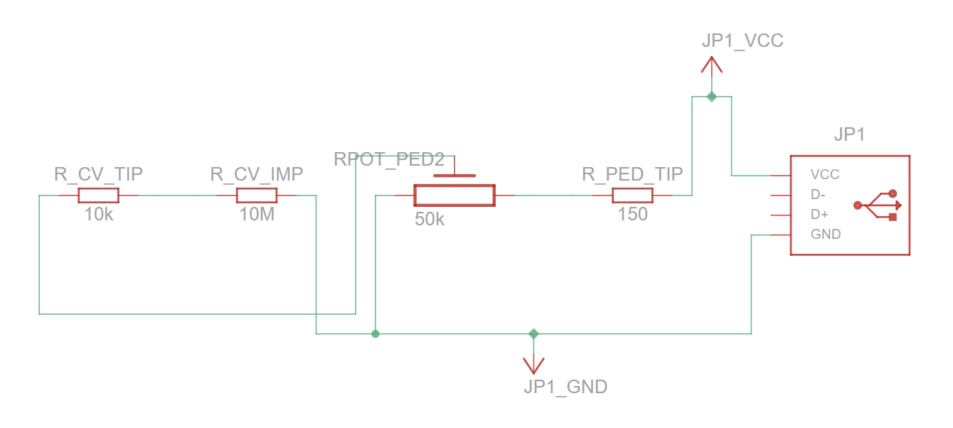
Tinkercad also sports a USB connector and all the resistors you can dream of. And that's the whole recipe for this "CV adapter". It took some time to remember my URIs (Ohm's law) and how things affect the dance of the electrons (or little green men if you prefer). To be honest I still don't really know, but fiddling and discussing with GPT got me to something that works with a fair understanding. Mr. GPT had suggested a 50 kΩ resistor between the pedal and synth, but the simulations led me to choose a 10 kΩ. Again, the learned and/or dilligent would bother to calculate why.
The ingredients for the simulation ended up as follows:
| Name | Value | Description |
|---|---|---|
| USB Standard A | - | USB connector. It gives 5V in the simulator as expected. |
| Resistor A | 150 Ω (several tries) |
A resistor to limit the circuit current slightly from the USB output. Just to be precaucious. |
| Resistor B | 10 kΩ | A resistor to protect and limit the current going into the synth. (We'd rather not blow it up...) |
| Fake CV in port | 1 MΩ | A resistor representing the internal impedance of the synth's CV sensor and the tip (VCC) and sleeve (GND) of the jack plug. |
| Multimeter | - | A multimeter in resistance mode measuring the loss over the "fake CV in port" resistor. |
| Fake pedal | 50 kΩ | A potentiometer representing the pedal and the tip (VCC), ring (CV out), and sleeve (GND) of the jack plug. |
Here's the breadboard layout:
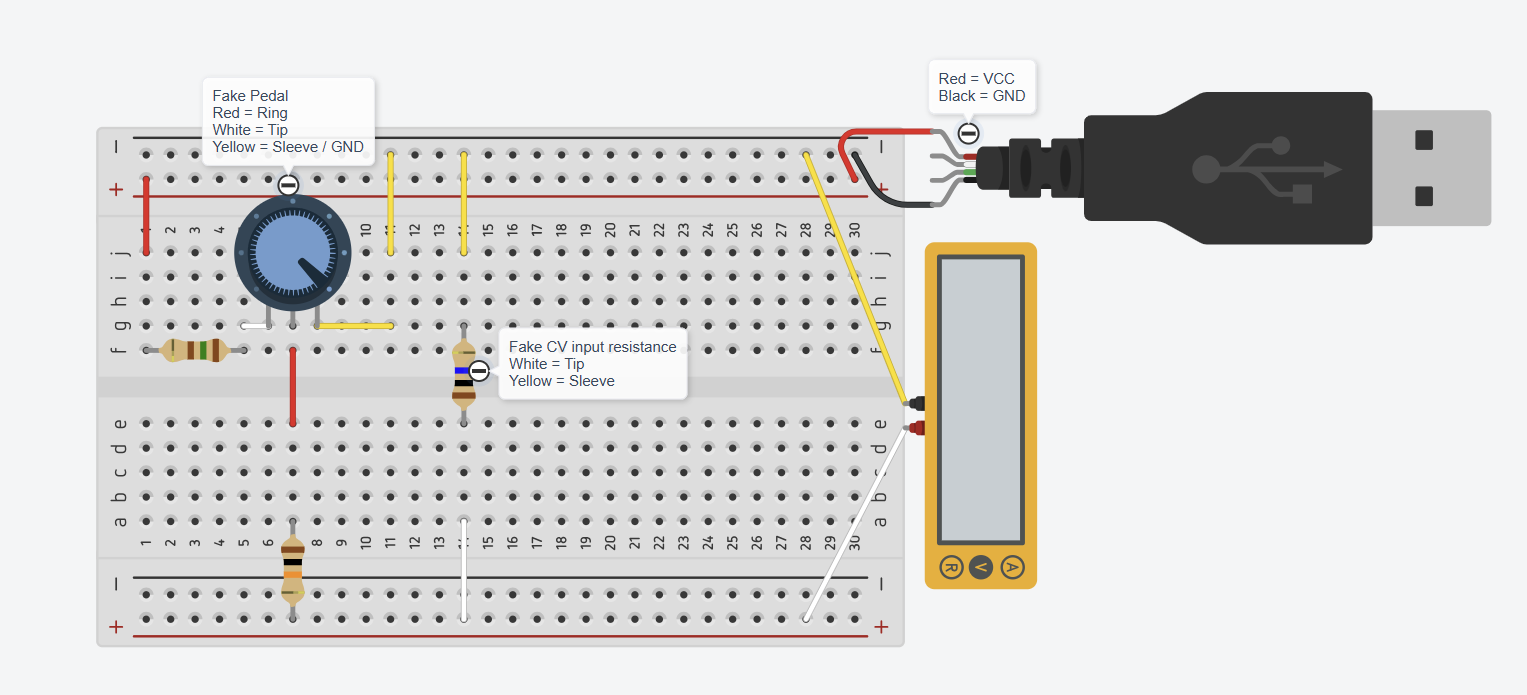
I'm extremely discontent with how Tinkercad figured to lay out the schematic, but in any case I suppose it is correct. Why couldn't the pot go straight to the 10k resistor? Oh well, here's it is in all it's jumbled glory:
Prototyping and building in real life
Having the simulation show thumbs up I figured I should try it in real life and do some measurements before hooking anything up to my brand new synth. For some reason Tinkercad shows a tiny explosion on the USB connector when the simulation starts, but my adapter stood the test and I suspect there might be a bug with the implementation on Tinkercad. 😇
I have both breadboards and a plethora of resistors lying around from my Arduino adventures last decade. Finding a breadboard and some resistors didn't bide much problem. They're all within arms length to my left. But this is where I started going back and forth between the breadboard and Tinkercad. Turns out real life didn't give the same measurements as the simulation. Even if I used a PSU of 5.5V instead of a USB connector. My adapter gives 5.5V, remember?
Here's a little montage of all the crocodiles holding things together.
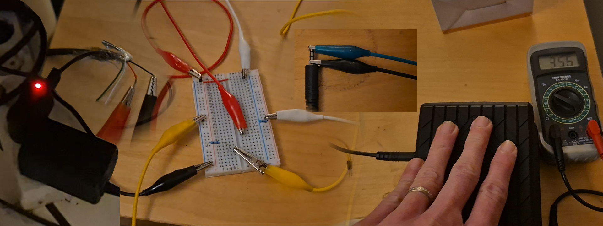
After a while I had the right resistors to see 0-5V on the multimeter having hooked up the pedal to my shortest mangled jack-cable. I excitedly hooked up some crocodiles to the other half-jack and the breadboard, wearily shoved the plug into my synth and tried the pedal. Sucess! The LCD-display on the synth showed 0 to ... 97%??? So even if the simulator and my multimeter showed I output 5V from the pedal when 100% down the Minilogue expects more. Anyone knowledgeable with electronics will likely know why, but I merely suspect that it somehow "feels" the max input from the source is 5.5V. So it was out with the jack, out with the GND crocodile and in and out with misc initial resistors until I saw 0-100% CV input on the synth. A 150 Ω resistor turned out to be the sweet spot.
I now had proof I could build this "CV-adapter", so it was time for V1.
Assembling V1
Again from my Arduino-days I found a few circuit boards in my drawers. The smallest ones were 24x18 holes (7x3cm) - a little big. But incidentally I could spot in the corner of my eye something resembling an Arduino-case. The 7x3 board fits perfectly within, and it's a slim one just 1.5cm tall. Perfect!
On to the soldering. Not that I lacked any space, but it's always nice not having to cross wires. Enter a slightly unorthodox tool, my favorite program in the whole world: Excel. Who needs technical drawing software when you have colorable cells? I first drew up the layout on the left, but inspecting the casing I'd found I figured I'd rather flip it around. So I ended up going for the layout on the right.
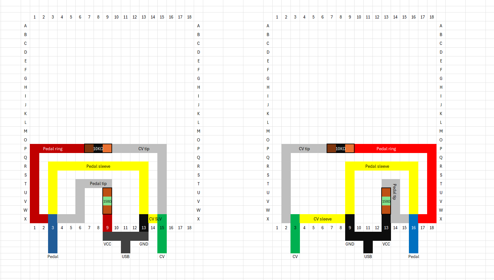
I'm extremely shaky, so soldering took its time. It's somewhat of a Zen excercise I've never quite mastered. I also realized way too late (of course) that I'd been better off stretching a few more wires, but hey - it's 10 years since last time I did anything like this.
In any case, the first test with the multimeter and pedal showed a semi-constant 5.4V so I had to go back to the soldering board. A few connection tests with the trusty meter showed a lacking connection to ground from the pedal. Even with my new "computer glasses" and a magnifyer on my little helper I couldn't see that the amputated resistor leg I'd connected to ground wasn't connected. But I could find the spot where the connection ended, so I added kind of a highway of tin all the way. Success!
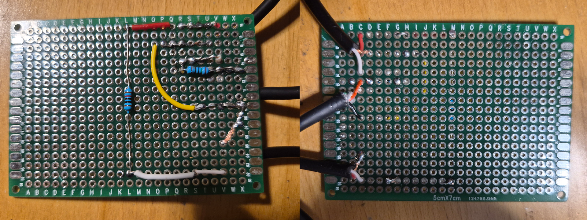
Here's how the circuitboard ended up.
The final stretch was to have the board rest well within the box. I was lucky to find some double sided tape in the kitchen, and since one side of the board already rested slighly on the USB and jack cables I chuckled as I cut off another 2.5cm piece of the now 4cm long USB mini cord. It fit perfectly. Tape on the case, tape on the board, and a short piece of USB mini cord as a pillow.
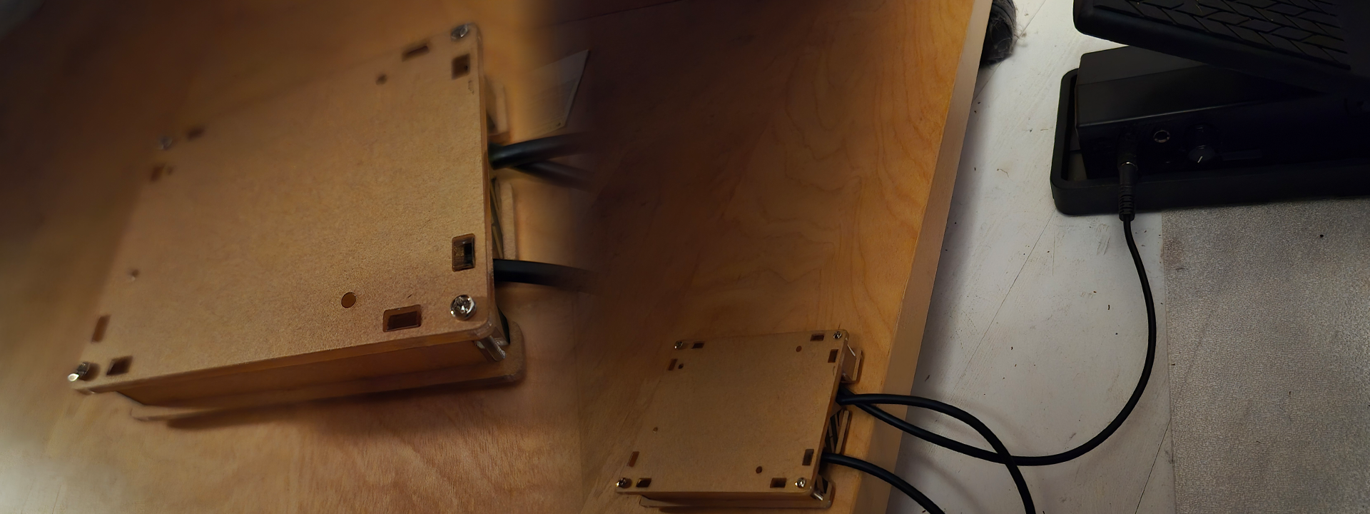
Here's the final box.
Final fun
Of course my box needed a name and a logo. It didn't take many brain-iterations until I landed on Larsingerlogue CV-5000. It's my [Behr]inger [FCV100 to Mini]logue[ XD] CV-5[V * 1]000[mA adapter]. I turned to my age old friend "Impact" and quickly found a fitting gradient in Photoshop.

Video montage
I'd also shot a couple of videos and pictures during the process, so I amused myself by throwing together a short video of the whole process. It features the first built in patch of Minilogue XD and it's sample sequence with me "playing" the filter cutoff on the now functioning pedal, and the "riser" delay time and depth using my free hand. Farily cool. And then a quite off-beat attempt at the Stranger Things theme as an RL demo of the final product. Check it out.
I hope you've anjoyed following my little story of dipping my toes in electronics for music. There's high potential for a V2 with better polarity support, and who knows what other ideas one might come up with for 100% "DIY" effects to shove into those CV inputs. There's still one unused. 😁
Grief
My only grief, and that's kind of connected to the single polarity of my adapter, is that all of the built-in patches in the Minilogue XD are set to having CV 1 modulating the shape of VCO 1 from 0 to 100%, and CV 2 is set to filter cutoff from 0 to -100%. That means I open the filter by "closing" the pedal and close the filter by "opening" the pedal. Pedal to the floor means almost no audible sound.
Learning while blogging
In hindsight I think I just realized with writing this that 5V on the multimeter means (almost) no power moves through the resistor, which is measured as 0V - while I've been reading 5V (loss) on the multimeter. That would explain the "weird" direction of the pot meter in the simulation that'd been bugging me. 🤣
But hey - adds to a fun story about learning and just jumping into the water.
If you got this far I hope you had a chuckle, nodded or otherwise found this interesting.
Thanks a lot for reading, and have fun whatever endeavor led you to this post.